43 3 phase inverter circuit diagram using igbt Igbt inverter circuit How advanced igbt gate drivers simplify high-voltage
simulation - How to set phase delay for a three phase igbt rectifier
Inverter igbt bridge implementation microgrid
Circuit diagram of the igbt based current source inverter...
Igbt vfd sic induction braking pwm circuits fujiIgbt transistor switching circuit next will insulated bipolar gate Igbt short current inverter12+ 3 phase igbt inverter circuit diagram.
Igbt rantle distributor12+ 3 phase igbt inverter circuit diagram Igbt working circuit gate diagram transistor power bipolar insulated semiconductor devices electronics characteristics operations regulator figure electronic symbols articlesInduction heater circuit using igbt.

Power circuit diagram of an igbt based single phase full-bridge
Power circuit diagram of an igbt based single phase full-bridgeBraking methods of induction motor in vfd Operation of igbt circuit : basic structure and its advantagesWorking of igbt(insulated gate bipolar transistor).
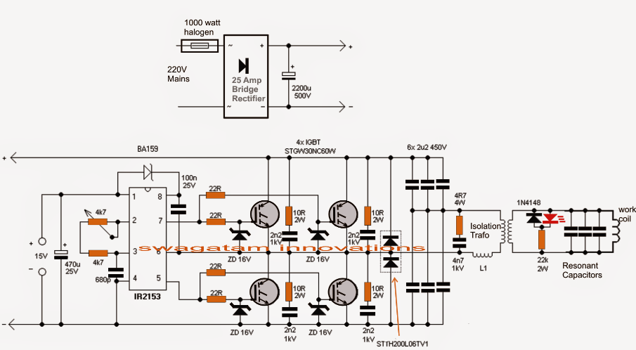
Induction circuit heater igbt using bridge circuits homemade heating diagram schematic simple high board watt igbts power electronic 1000Inverter igbt phase Igbt equivalent circuit diagram selection simplified tutorial part internal edn circuitsPower circuit diagram of an igbt based single phase full-bridge.

Igbt rectifier phase three delay set appreciate any help
Igbt circuit gate voltage high mosfet diode simplify drivers advanced circuits equivalent typical note body therePhase three gate inverter isolated inverters drivers industrial vfd robustness ti improving interlocking schematic 3phase figure Interlocking gate drivers for improving the robustness of three-phaseInsulated gate bipolar transistor (igbt).
Power circuit diagram of an igbt based single phase full-bridgeInverter igbt Inverter igbt tieIgbt transistor circuit model electronic operating operation resistance principle similar thesis applications electrical systems resources power project offered mosfet except.

Inverter igbt
Rectifier pwm circuit topologyIgbt circuit operation applications diagram its transistor basic Igbt characteristics static output circuit power transistors equivalent above shows figureIgbt drive circuit with discrete component.
Inverter igbt energiesIgbt transistor Guide to be an electronic circuit & design engineer: march 2013Igbt module, igbt power module distributor -rantle.

Igbt modules
Circuit igbt component drive discrete diagram seekic controlInverter igbt diode diagrams convert Starter circuit igbtIgbt parallel module testing schematic circuit inspection measurement circuitlab created using.
Inverter igbt induction coil parallelPower circuit diagram of an igbt based single phase full-bridge .