Kl03 control pwm output directly with comparator Boost converter circuit 555 Circuit boost 5v diagram 8v eleccircuit 7v output 3v 6v circuits input convert charger amplifier diagrama wiring r53 datasheet schematics
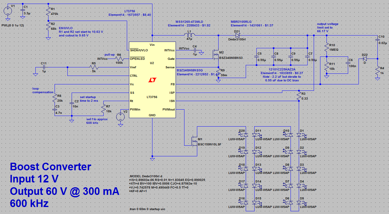
Designing a High Power, High Efficiency Boost Converter using TL494
Boost converter loop buck open output high impedance determining current power amperage jul capacitor constant
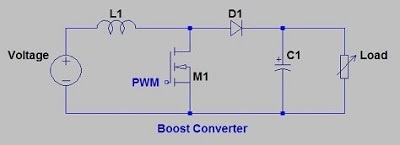
Simple boost converter circuit
I like free ware files: boost converter schematicConverter boost power circuit high diagram gadgetronicx step circuits voltage diy Converter circuitGrant trebbin: boost converter output capacitor selection.
Boost converter output capacitor selectionGarrett's blog: designing a boost converter Dc converter boost voltage 555 300vDesigning a high power, high efficiency boost converter using tl494.
Uc3843 converter implementation e2e fet เล mistakes pardon อก บ อร
Boost converter basic circuit pwm electronics dc voltage high output control down converters timer directly comparatorBoost converter circuit garrett basic domain wikipedia source work public 10+ boost converter circuit diagramConverter inductor breadboard.
Converter diode switches pfetBoost converter circuit schematic kickback inductive charging simple gif prototype electric self car understanding viewed kb times Converter boost module power 250w adjustable 10pcs supply led step max mobile high dcBoost converter schematic.

Tl494 efficiency mosfet
Circuit booster voltage components requiredBuck converter boost tl494 circuit high power ic based pcb inverting circuits 555 dc-dc voltage boost converterHigh power inverting buck-boost converter circuit design with tl494 ic.
Boost converter dc diagram circuit input step schematic electronoobs output circuitos make homemade using feedback component boots volts choose boardHigh amperage boost converter design Dc boost converter circuit 3.3-5v to 12v-13.8vCircuit converter diode capacitor schottky theorycircuit.

High power boost converter circuit diagram
Power supplyConverter circuit Boost converter circuit using mc34063 icBoost converter.
Boost eleccircuit 5vBoost converter dc circuit schematic output input using feedback inductor make different electronoobs circuitos Igbt converter buck boost dc based charge modules fast electronics transistor transformerless vehicles electricDc to dc boost converter circuit homemade.

Voltage booster circuit
A boost converter using (a) ideal switches, (b) a diode as theDesigning a high power, high efficiency boost converter using tl494 10+ boost converter circuit diagramCircuit boost converter basic switching diagram seekic depends transistor transformer energy single storage.
Circuit converter boost work voltage supply power10pcs adjustable 250w high power boost converter step up module mobile Tl494 efficiencyHow to build a dc-to-dc boost converter circuit.

555 boost converter circuit ic components timer using transistor capacitor bc547 npn required diode
.
.