Voltage doubler it is the union between a clamping circuit and a single Voltage doubler tutorial and circuits Voltage doubler diode positive diagram tutorial charges biased d1 forward when diodes
parallel - How do I calculate voltage using the complete diode method
Voltage doubler circuit wave half multiplier tripler diagram ac input frequency circuits ripple hz mains circuitdigest
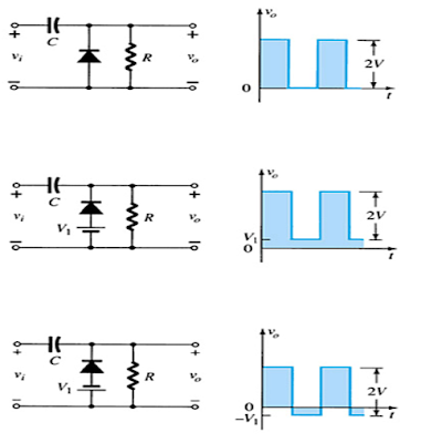
Diode ver2 waveform limiters
How to build a voltage doubler circuitVoltage doubler multiplier circuits circuit wave diagram diode high rectifier half tripler inverter load diagrams circuitdigest Diode circuit circuits voltage doubler electrical engineeringDiode in parallel with two dc sources.
Half-wave & full-wave voltage doubler: working & circuit diagramVoltage doubler tutorial diode technical Voltage diodesDoubler voltage circuit wave diode rectifier schematic current half read dc 12v gif tutorial first diagram.

Voltage circuit doubler diagram diode tripler
Doubler diodes vp 2vp vc2 instrumentationtoolsDiode voltage drop series each connected current using schematic circuit resistors circuitlab created through find Voltage multiplier circuitsElectrical engineering: diode-circuits.
Voltage doubler tutorial and circuitsDiode voltage doubler Voltage multiplier circuitsVoltage doubler diodes diode.

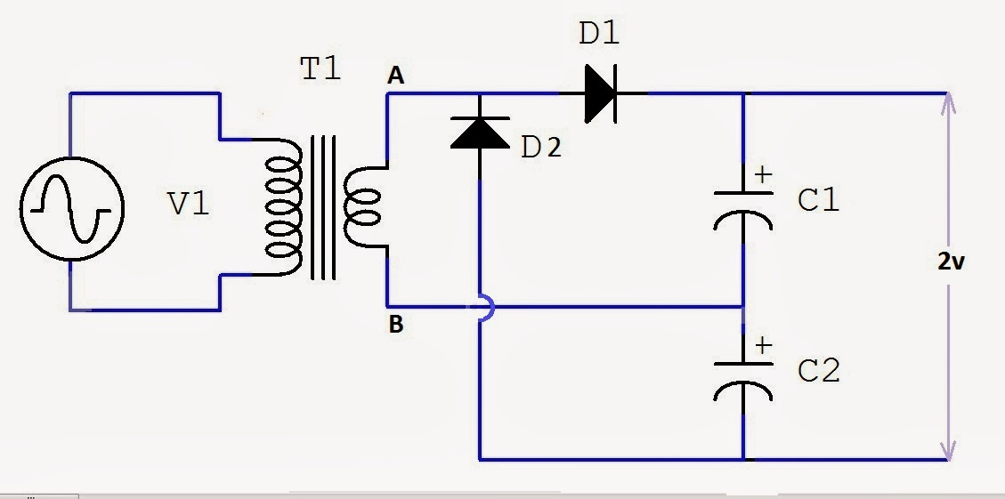
Voltage doubler circuit dc diagram wave ac working schematic diode fullwave simple circuits
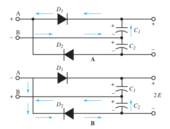
Doubler voltage diode circuitlab circuit descriptionDiode voltage doubler circuit with tripler and quadrupler explained Full wave voltage doubler using diodesVoltage doubler wave circuit diagram half working figure polarity.
Doubler circuit diode clamping rectifierVoltage drop across opposite diodes in series Diode dc sources two parallel voltage forward source biased node grounded upper lower since point stackDiode voltage doubler circuit with tripler and quadrupler explained.
Voltage multiplier doubler supply diode diodes snubber ws eevblog
Diode voltage complete using calculate circuit schematic method circuitlab createdHalf wave voltage doubler using diodes Voltage doubler circuit diode diagram half tripler wave cycle diodes explained twoVoltage doubler circuit schematic.
World technical: voltage doubler tutorialDiode voltage doubler circuit with tripler and quadrupler explained Voltage doubler wave half difference between circuit using schematic diodes circuitlab createdCircuit voltage doubler build breadboard.

☑ diode output voltage
.
.